How Engineers Interpret FM Approval Data for Seismic Bracing Systems
 1. FM Approval as a Performance-Based Certification
In seismic bracing design, FM Approval is widely recognized as one of the most stringent and credible certification systems.
Unlike purely prescriptive standards, FM 1950 is fundamentally performance-based:
It does not only define geometry or material requirements
It evaluates how a bracing system behaves under load
It generates measurable performance data for engineering use
For this reason:
FM Approval provides not just compliance, but quantified performance characteristics.
To use this data correctly, engineers must understand how it is generated — particularly in seismic testing.
2. What FM Seismic Tests Are Designed to Capture
FM seismic testing focuses on the mechanical response of a bracing assembly under increasing load.
Rather than producing a single “strength value”, the test establishes a force–displacement relationship, which reflects:
System stiffness under initial loading
Progressive deformation behavior
Load resistance as displacement increases
This relationship is essential because seismic performance is not defined by a single peak force, but by:
How the system resists movement over a controlled displacement range
3. The Role of Displacement Limits in FM Testing
A defining feature of FM seismic testing is that it does not continue until structural failure.
Instead, the test is terminated at a predefined displacement limit.
This is not a limitation of the test — it is a deliberate engineering decision.
3.1 Displacement as a Governing Design Parameter
In piping systems, excessive displacement directly leads to:
Loss of alignment
Increased stress at joints and fittings
Interaction with adjacent systems or structures
Because of this, seismic design standards treat displacement as a controlled variable, not just an outcome.
3.2 Functional Performance Boundary
The displacement limit used in FM testing represents a functional boundary condition:
Within this range → system performance is considered acceptable
Beyond this range → system reliability cannot be assured
This means:
The test is focused on the usable performance range, not ultimate collapse behavior.
4. Load at Displacement Limit: The Key Engineering Parameter
At the moment the displacement limit is reached, the corresponding load is recorded as:
Load at Displacement Limit
This value is the most critical output of FM seismic testing.
4.1 Why This Parameter Matters
This load represents:
The maximum force the bracing system can deliver
While maintaining displacement within acceptable limits
From an engineering perspective, it defines:
The effective seismic restraint capacity of the system
4.2 Difference from Ultimate Strength
It is important to distinguish this from ultimate strength:
Ultimate strength → failure-based
Load at displacement limit → performance-based
A system may have high ultimate strength but still perform poorly if:
It allows excessive displacement before reaching that strength
5. Interpreting Differences Between FM Approved Systems
FM Approval ensures that systems meet minimum performance requirements.
However:
It does not eliminate performance variation between different products.
Two FM Approved bracing systems may:
Reach the displacement limit at different load levels
Exhibit different stiffness characteristics
Provide different levels of restraint within the same displacement range
5.1 Engineering Implication
For design purposes:
A higher load at the same displacement limit indicates stronger restraint capability.
This directly affects:
The system's ability to control movement
Load distribution across braces
Overall system reliability
6. Using FM Test Data in Seismic Design Calculations
To apply FM test results in real projects, engineers must integrate them into seismic design calculations.
In FM-based design approaches (such as FM 2-8):
Seismic demand is calculated based on pipe mass and acceleration
Bracing capacity must be verified against this demand
6.1 Capacity vs Demand Framework
The design condition can be expressed as:
Restraint capacity ≥ Seismic demand
Where:
Capacity is derived from load at displacement limit
Demand is derived from seismic load calculations
6.2 Impact on Layout Decisions
This relationship directly influences:
Brace spacing
Higher capacity allows:
Increased spacing between braces
Reduced total number of supports
Load distribution
Stronger braces can:
Carry higher loads per location
Simplify system layout
Design efficiency
Optimized capacity usage leads to:
More efficient material use
Improved constructability
7. From Certified Data to Real System Performance
While FM testing provides reliable component-level data, real-world performance depends on how that data is applied.
Key variables include:
Installation angle
Direction of loading (longitudinal vs lateral)
Pipe size and weight
Interaction between multiple braces
This introduces a critical requirement:
Accurate translation of test data into system design
8. Engineering Integration: Bridging Testing and Design
In practice, this translation requires:
Interpreting FM-certified performance values
Applying them within FM 2-8 calculation frameworks
Converting results into detailed layout drawings
Because of the number of variables involved, this process can be:
Calculation-intensive
Sensitive to input assumptions
Difficult to standardize manually
As a result, engineering tools and design methodologies play an increasingly important role in ensuring consistency and accuracy.
9. A Structured Approach to Seismic Bracing Selection
An effective engineering workflow typically includes three aligned steps:
1. Certification Verification
Ensure the system is FM Approved and project-compliant
2. Performance Evaluation
Compare key parameters such as load at displacement limit
3. System Design Application
Translate performance data into a complete and compliant bracing layout
Only when all three are addressed can the system achieve:
Regulatory compliance
Reliable performance
Practical constructability
10. Conclusion
FM seismic testing is designed to define the usable performance range of a bracing system.
By stopping at displacement limits provides a clear answer to a critical engineering question:
How much force can a system deliver while maintaining acceptable displacement?
For engineers, the implication is clear:
FM Approval establishes credibility and compliance
Load–displacement data defines actual performance
Proper design application determines final system behavior
Understanding this framework is essential for selecting and designing seismic bracing systems that perform reliably under real seismic conditions.
Related Products
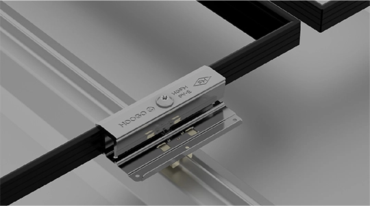
FM Approved Roof-Mounting PV Module Systems
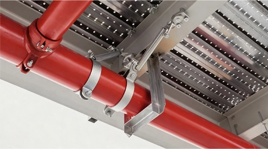
FM Approved Seismic Bracing Systems